Capacitor Holder
-
Bend the leads on the super caps at right angles so the negative will
go into the '-' hole and the printing of the super cap values is
visible. The capacitor wires protrude out the bottom beveled edge.
-
Insert two of the caps into the end slots, slip the wires into their
respective holes and set the clip in place.
-
Slide the caps in the clip until the beveled edge of the clip just
clears or almost touches the U6..U10 devices as in this photo
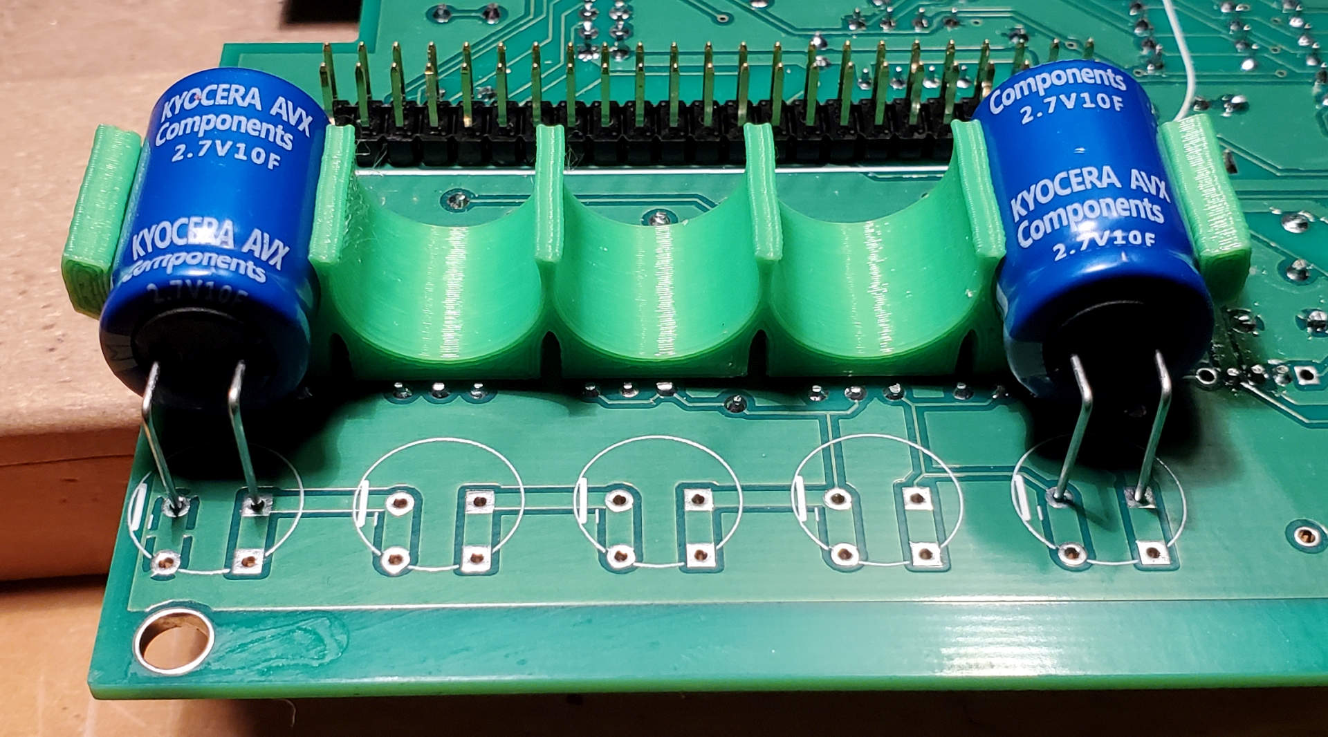
The slots underneath the clip are on 0.1"
spacing and should then clear the other component pins. Trim any that
are too high with flush cutting pliers. The act of trimming closely to
the board can mechanically break the solder connection so for any that
look suspect, touch them up with the soldering iron.
-
Use a hot melt glue gun to push glue along the edges that don't have
the capacitors and at the ends staying clear of the two that are sitting
in the clip. The vertical slots in the clip well allow glue to
penetrate under the clip.
-
When the glue is cold remove the two capacitors, add more glue in the
area where they were. It will look something like
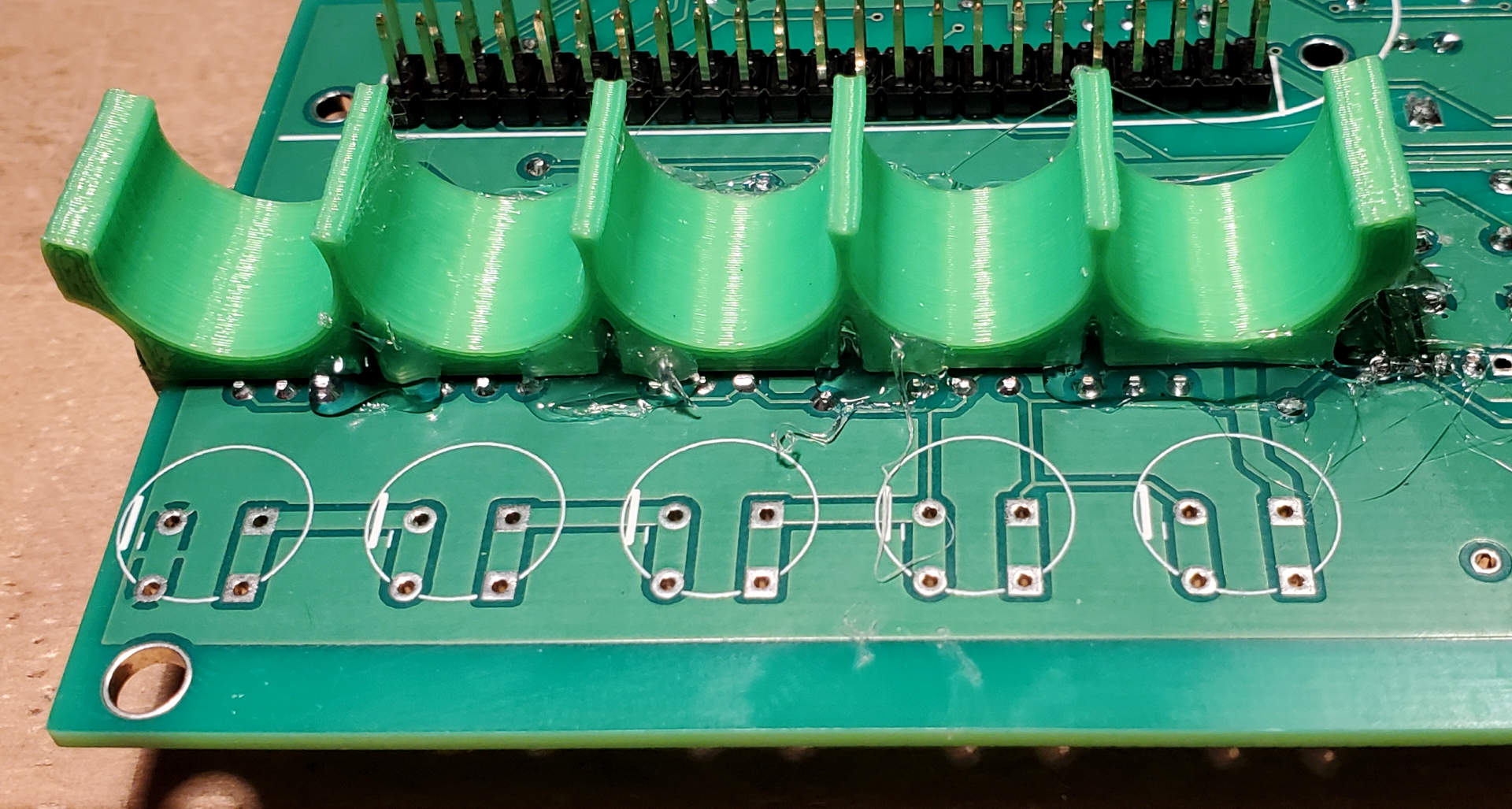
-
Now insert all 5 super caps and solder the leads and trim the leads
on the other side.
Feel free to contact me, David Gesswein djg@pdp8online.com
with any questions, comments on the web site, or if you have related equipment,
documentation, software etc. you are willing to part with. I am
interested in anything PDP-8
related, computers, peripherals used with them, DEC or third party, or
documentation.
PDP-8 Home Page
PDP-8 Site Map
PDP-8 Site Search