Top level page
I used a
Vidicon
based Panasonic WV-1400 video camera made around 1980. It
outputs standard
interlaced composite video. The PDP-8 has the A/D converter
and digital I/O board that is part of the Lab 8/E option.
The A/D converter is 10 bit with maximum 50 kHz sample rate.
Composite video has 15.75 kHz line rate so at best could sample 3 pixels per
video line.
To allow the video to be captured
I made a sample and hold board that
can capture the desired pixel which is about 80 nanoseconds wide
from the video line and hold the voltage
for long enough for the A/D to convert it. To simplify implementation I
sample maximum of one pixel from each line each field. It ignores the
chrominance signal if present.
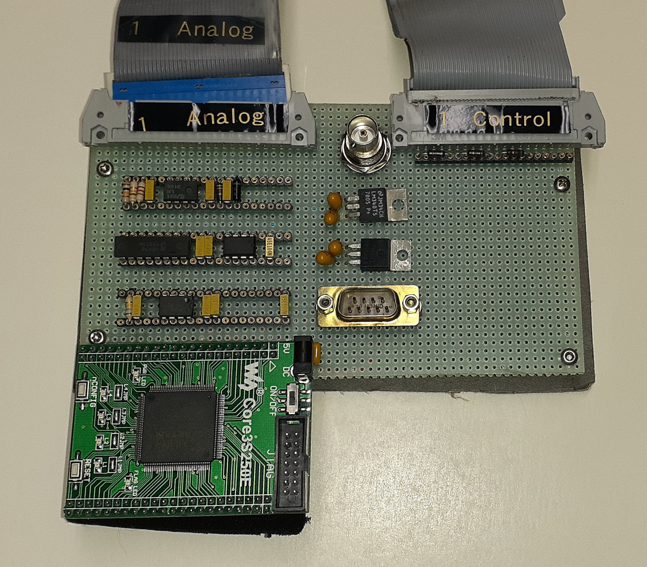
The board has a phase locked loop (PLL) chip I was going to use to generate a synchronized clock for sampling but I couldn't get stable lock when I made it in 2017. I switched instead to using a 100 MHz clock to time sampling from the horizontal sync edge. It worked well enough that I didn't try again to fix the PLL for this demo.
Board is obviously not made with period components. It would have been possible to make it in the 70's but would have been a box of boards. The fast sample and hold would have been the difficult portion. Analog devices had 25 nanosecond sample and hold part HTS-0025 sometime before 1980.
The sample and hold board is programmed to support 3 video formats. The control cable from the PDP-8 selects the format and triggers the start of capture. The analog cable is the sample and hold output. The 9 pin connector is input power. Two formats are for ASCII art, 132x79 landscape that prints on one page and 132x140 portrait that prints one page wide and two pages high. The sampling was adjusted to match the printed aspect ratio of 10 characters per inch and 8 lines per inch. It can also capture 640x480 full resolution image from the two interlaced fields.
For the ASCII art version it uses the PDP-8 memory fields 3-7 to capture the image then uses normal OS/8 file IO calls to write it to the desired device. Parts of fields 0-1 are used by OS/8 and at least TD8E and RX02 system device handler uses part of field 2 so they weren't used.
The 640x480 picture version is hard coded to write to TM8E controller for the TU10 tape drive. It interleaves reading ADC and writing blocks of data to tape. Not sure why I didn't use ADC interrupt instead of polling. The data is written in the TM8E special 7 track format to keep the 10 bit ADC data. That writes each memory word as two 6 bit values to the tape so cuts the data rate of the drive in half. Good tapes were originally shipped error free. I don't know if my drive margins have decreased or my tapes aren't great but with most of my tapes I get a few write errors over the length of the tape. With the 640x480 RGB pictures using 230 feet of tape I was hitting write errors often enough to be annoying. The full size tapes I used are 2400 feet.
The drive does read after write check with threshold shifted to be more sensitive to detecting dropouts. The normal OS/8 code just reports an error when this happens. The drive can hide the bad spots by backing up over the bad record and writing it again with 3" inter record gap instead of the normal 1/2". As long as your record is less than 2 1/2" the bad spot will be hidden in the gap. At 800 BPI that is 2000 characters or 1000 words when operating in 7 track mode. I write 1024 word blocks which is close enough.
TU10 drive is 45 inches per second which gives a peak data rate of 36,000 characters per second. In 7 track mode and taking into account the record size the effective transfer rate is 15,000 words per second. At the 640x480 resolution the average ADC data rate is 14,400 words per second so not a large margin. To keep up the drive has to be kept streaming. I had to optimize the code path from checking last operation done to setting up next to keep drive streaming. Using fields 3-6 for buffer it can handle a write error without losing data. Field 7 was giving me EMA 7 inc errors from the controller so I didn't use it. Need to look at that further.
Both programs advance to end of tape when started so new pictures will be appended to the tape unless told to start writing without repositioning the tape. I had a program that would dump the tape to my laptop which I ran periodically. I had an Omni USB board in my PDP-8 which can send the data about as fast as the tape can read it. Board is no longer sold.
I had a Octave program to convert the image captured by the PDP-8 to PNG. Since PNG didn't exist during PDP-8's prime time didn't think I needed to write PDP-8 code to generate it. I also added code to attempt to align the RGB pictures. Helped with some of the images. Some people were able to hold still well enough that alignment was fine without adjustment and others' movement wasn't uniform so only helped part of the picture.
The conversion to ASCII art and driving the line printer was done with a program in the PDP-8. It uses OS/8 handler to read the image back into memory and then generated a histogram of intensity. The range of intensities captured is used to rescale the pixels to the number of elements in the ASCII table data. Possible improvement is using the histogram to clip some of the darkest and brightest pixels to discard outliers. I scanned the printer font and tried to generate "best" encoding but it didn't look better than a character set I found online. Can't find where I got it from now. More work for next time I do this demo.
The historic ASCII art pictures were from a tape I got when working at Comsat Labs IBM mainframe computer center in first half of 1980's. I got a box of Teletype art at a hamfest where I put some samples on the tape. PDP-8 has a program MCPIP that can write named files to the tape and retrieve them. I first tried writing the tape on the PDP-8 but the program always rewinds to the beginning of the tape before appending the new file so would take a long time to write. I created it under the SIMH PDP-8 emulator and then wrote a program to write the SIMH tape image to the real tape. Also printed reduced size samples so people could see what pictures were available. Nobody this time asked to have any printed. I printed a couple for demo. Some more info on the pictures. The Teletype art had some likely read errors on the tapes so they aren't online yet. SIMH tape image
All the files are in this archive. See FILELIST.TXT for what the files are
in this archive. Sorry not well documented or
commented. Feel free to ask questions if you try to use anything.
Feel free to contact me, David Gesswein djg@pdp8online.com with any questions, comments on the web site, or if you have related equipment, documentation, software etc. you are willing to part with. I am interested in anything PDP-8 related, computers, peripherals used with them, DEC or third party, or documentation.
PDP-8 Home Page PDP-8 Site Map PDP-8 Site Search