The Texas Instruments Portable Professional Computer (TI PPC) is a
portable version of the
TI PC.
I have shown at previous VCF events. It is portable in the sense that
they put a handle
on it. It weighs 44 pounds so you're not going to want to carry it very far.
This machine is owned by the
VCF Museum @ InfoAge Science Center.
VCF Demo software
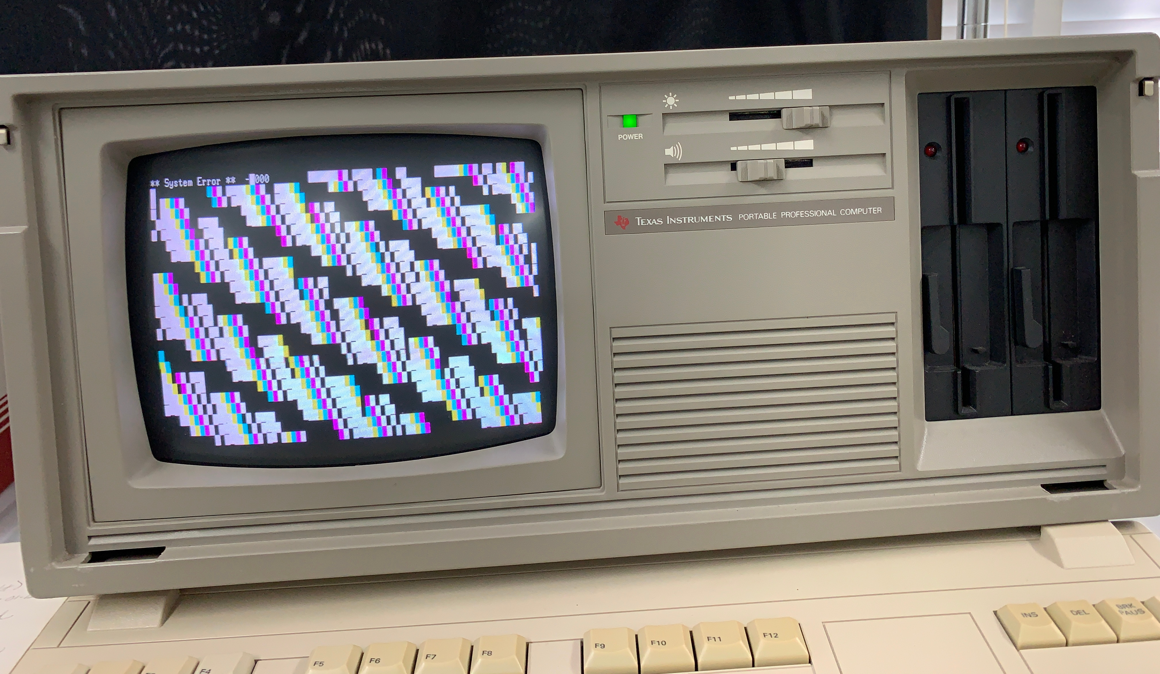
The machine was mostly functional but the screen was displaying junk. The
video error is a fatal error so it didn't try to boot.
I agreed to take it home and see about fixing it. Seemed like it should be
reasonably simple but like always a little more complex. Testing, the pattern
varied some between power cycles and once got the full error message at the top
of the screen indicating video error. The LED's also indicated video failure.
The BIOS ROM listing documents the errors.
The LED codes and error codes are at the start of ROMERR.SRC. Video error codes
are in CRTTST.SRC. The parallel port error bits are defined in TSTERR.SRC.
The machine drives the parallel port data pins with additional error
information. Probing them showed attribute memory error, character memory
error, and sometimes video output failure.
Schematics are in
technical reference manual.
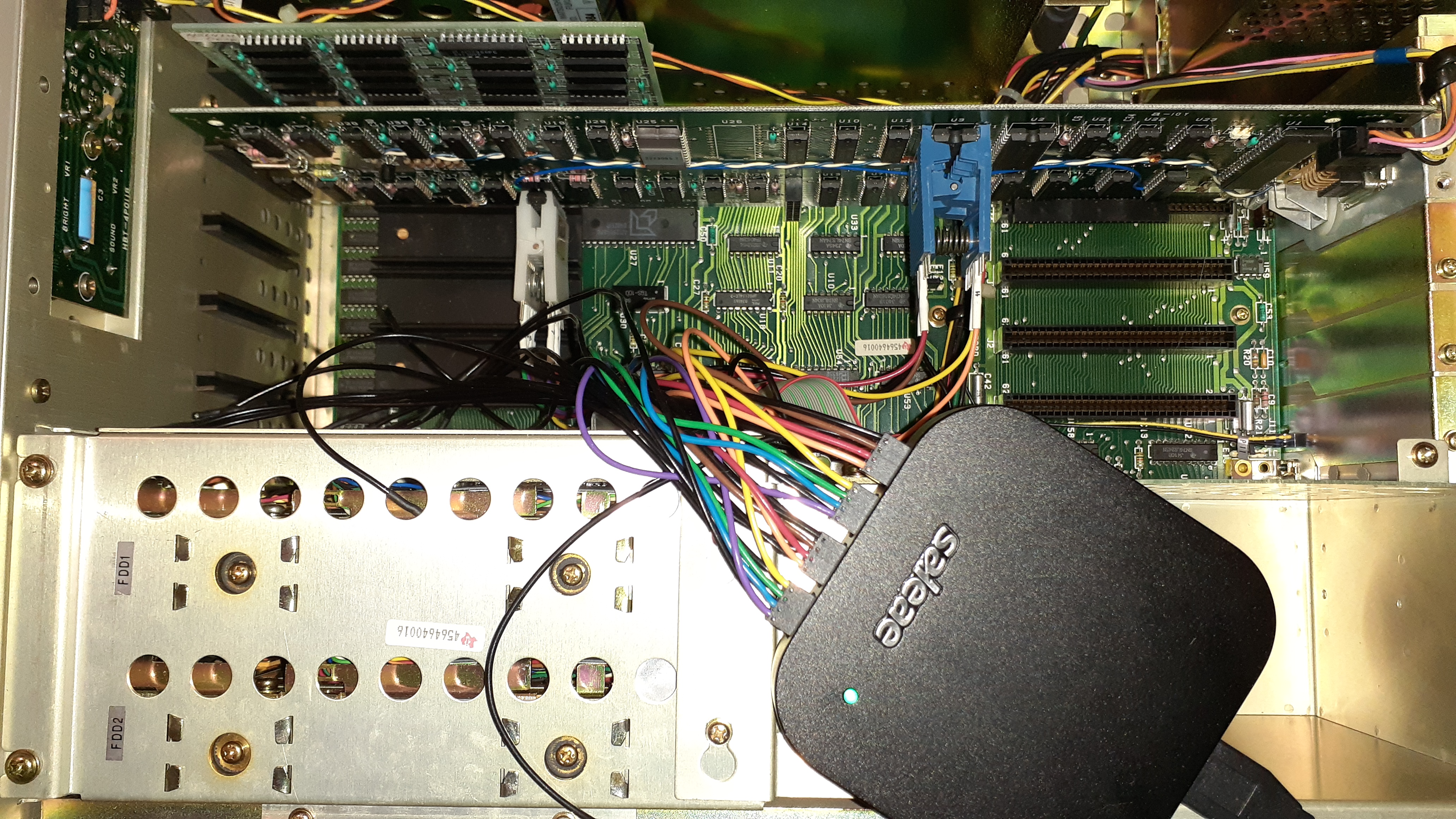
I thought it would be a bad memory chip so
hooked up the logic analyzer to the chip but the data read matched the
data written so the chip is fine. Looking further through the logic
analyzer data I noted that when the memory writes were closely spaced, I
saw several
writes that made it to the SRAM and then a number that didn't. This matches the
screen picture where you see some good blanks then messed up etc.
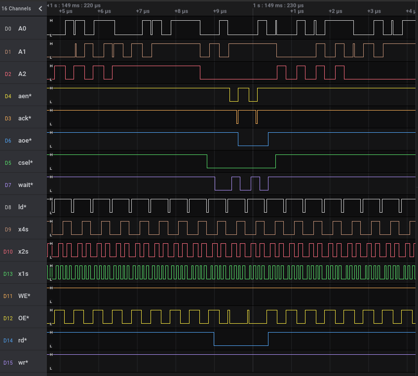
Bad cycles
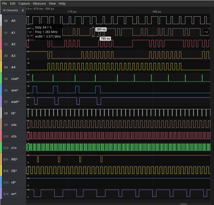
Video board is same between portable and normal TI PC except portable one had
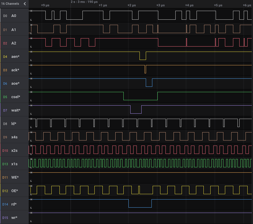
internal video connector added. Now the same memory cycles from good board.
You can see csel* is generating indicating the board thinks a memory access is addressing the board but aoe* is not always generated. You can also see that aoe* is mostly low but on the good board its mostly high. Not shown but earlier memory writes that are further apart the signals behaved the same on the two boards. Looking at the BIOS listing the fast cycles are generated from REP instruction.
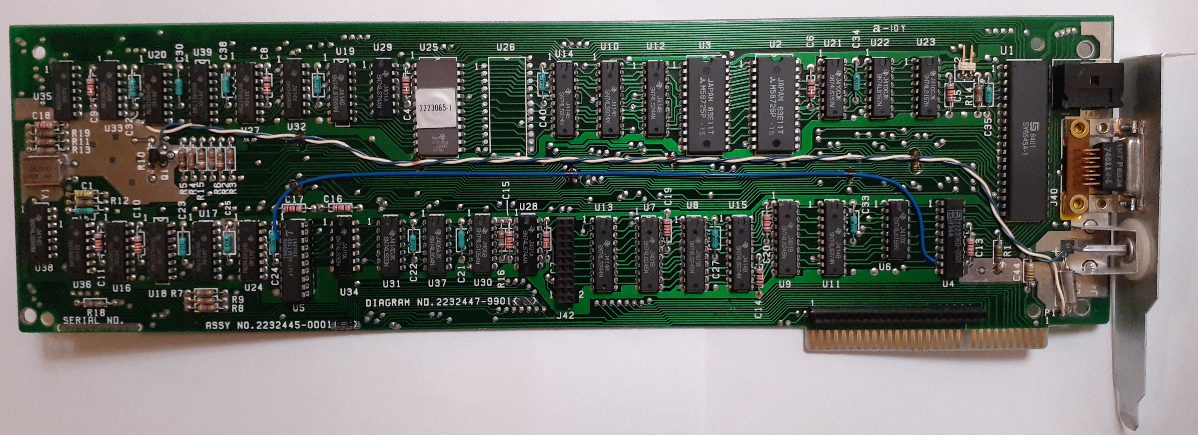
The control logic is in PALs U4, U5 and state counter U24. The rework between U4 and U5 prevented using DIP clip but with more probing I decided U5 was bad and pulled the chip. Soldered on a pin to U5 to replace the portion cut off and tried to read it in my programmer. Didn't get useful contents. The part is a HAL mask programmed part instead of the PAL fusible link part. Could be the read-back is disabled or HAL's can't be read.
The technical reference manual has listing for U5 fuse map in table 2-16. I coded it up and created an ABEL source file for it. That's what I used at the start of my career when PALs were the new chips I was designing with. I wrote the equations in positive logic and declared the active low pins using the ABEL syntax. That's what I like though in this case just implementing as the table may have been simpler. I used my DATA I/O UniSite to program a GAL16V8 I had in my chip stash to replace the HAL 16R8.
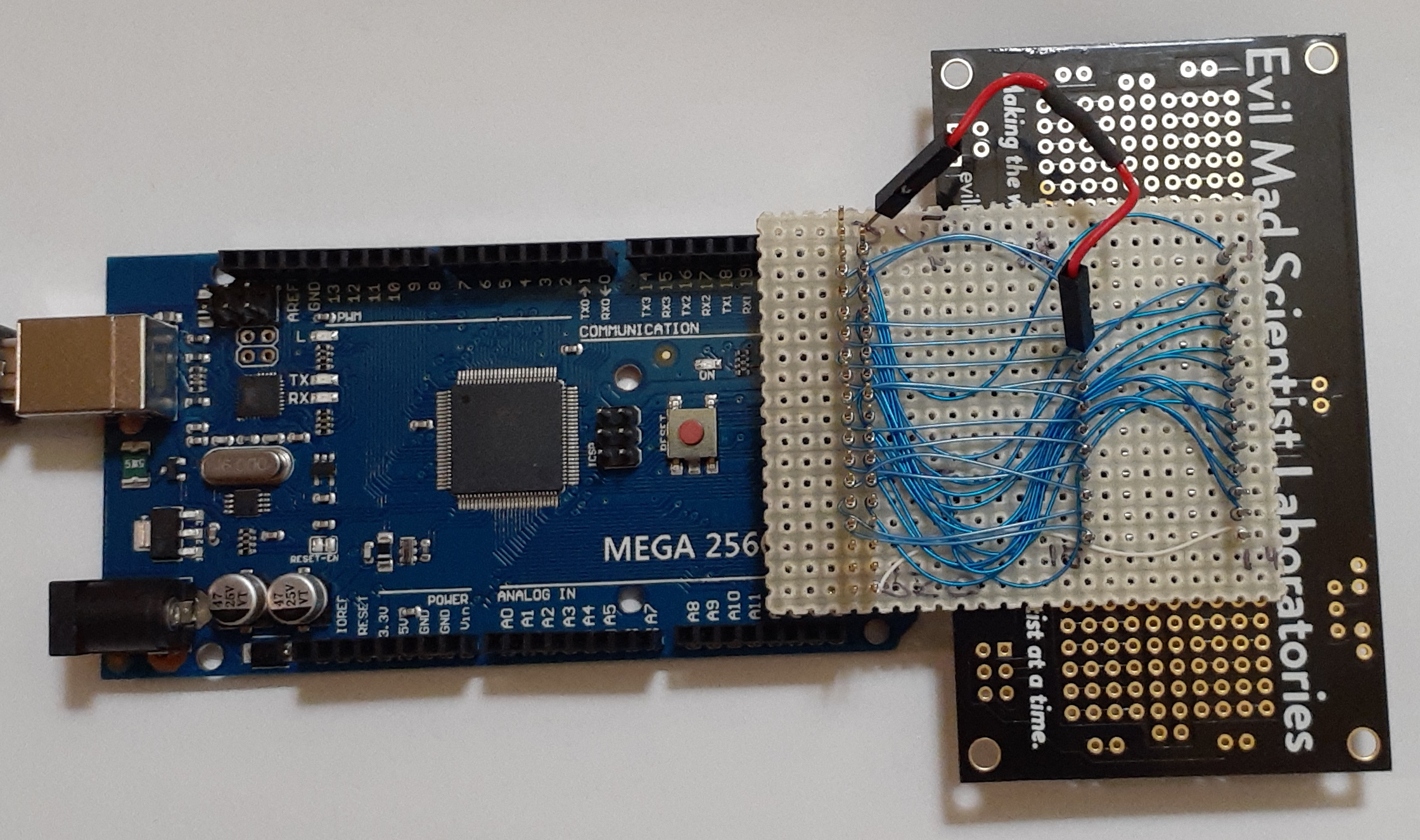
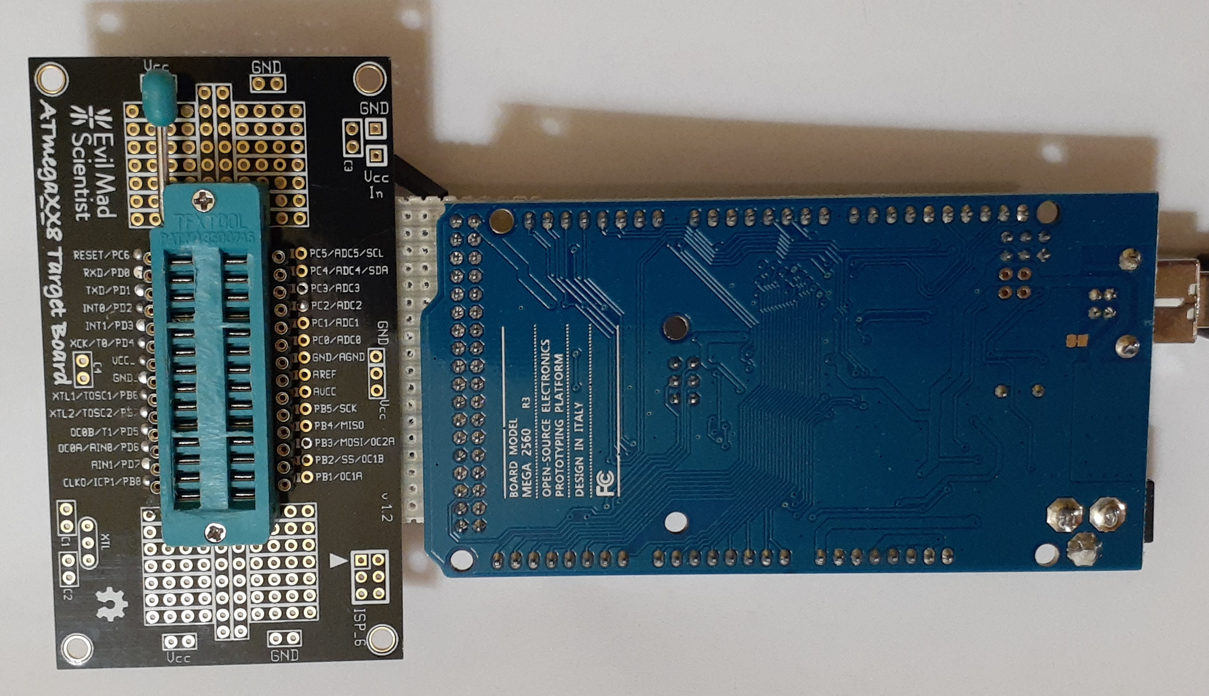
I didn't trust my conversion or that the manual was correct so decided to see what I could do with test patterns to compare the mostly working part to my newly programmed part. Local Micro Center had Inland Mega 2560 Arduino compatible board and Evil Mad Science ATmegaXX8 Mini Dev Kit - ZIF Socket I wired up to make a tester. It would have been more effective if I generated the high voltage waveform for preloading the output registers but to save time didn't try to implement that. I also wanted to be able to convert the test vector data back into equations. Searching around espresso logic minimization program was in my Linux distribution repo. That's the program I used back in college a long time ago. Didn't see anything newer so wrote my code to output the test data in format for that program.
Tested with some 7400 logic chips and when got proper equations for them tried the HAL and GAL. Equations looked similar to what I wrote but didn't match. I varied all the inputs and drove the state counter in expected pattern but not all internal register states were reached. The ones not reached were treated as don't care which changed the equations.
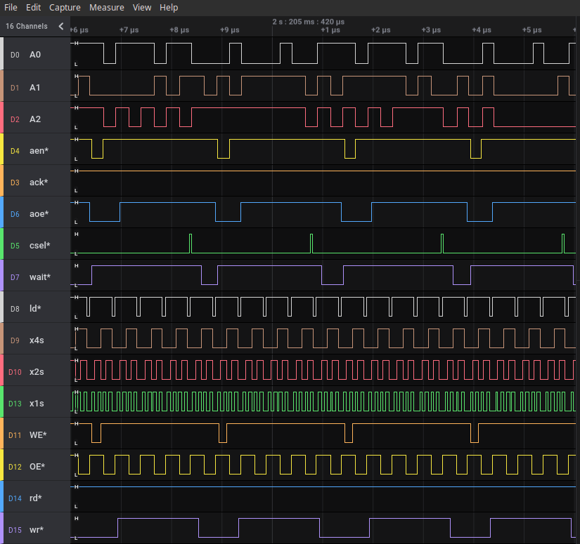
More concerning was that some of the outputs were different with the same inputs. I put a socket on the video board since expected several tries were going to be needed. Tried the GAL and visually the screen looked good. The machine now passed power up tests and booted. With the logic analyzer I could see the signal timing didn't match my good board. You can see the multiple pulses on aen*, ack*, and wait* that weren't present on the good board and the cycle took longer.
Looked like wait* was the problem. It shouldn't go high during the cycle. In the state machine PAL fuse map table it used different logic for the write cycle and the read cycle. The equations from espresso of the HAL part showed the read and write terms were identical.
wait- = (!csel-&!rd-&aoe-) | (!csel-&!wr-&aoe-) | (x4s&!ld-);I changed the read cycle to only use aen* like write and the test vectors now matched the HAL and the read cycle timing now matched my good board. Looks like the manual had an early version of the logic before they finished debugging.
My desktop had a RIFA cap smoke so I tried to check for them. A number of the shields and parts use slotted/keyhole holes so you can just loosen screws to remove them. Was able to pull power supply but cover didn't want to come off. From looking through holes it looked like they used ceramic capacitors and a power line filter so put it back together.
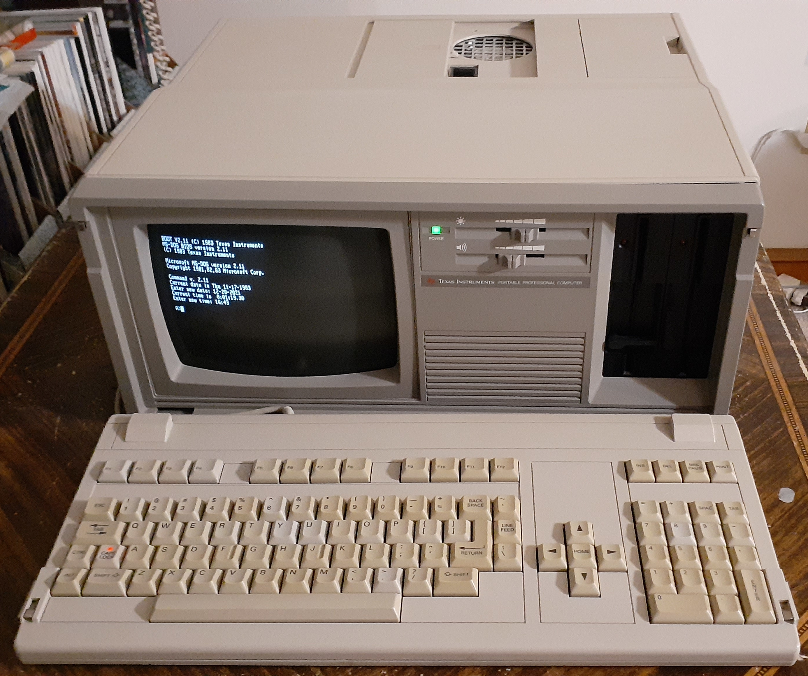
The machine now is fully functional. It has 256k memory, dual floppy drive with character graphics board. As you can see it has the color monitor option.
The u5 ABEL and jed files along with other PROMS I read are on my site.
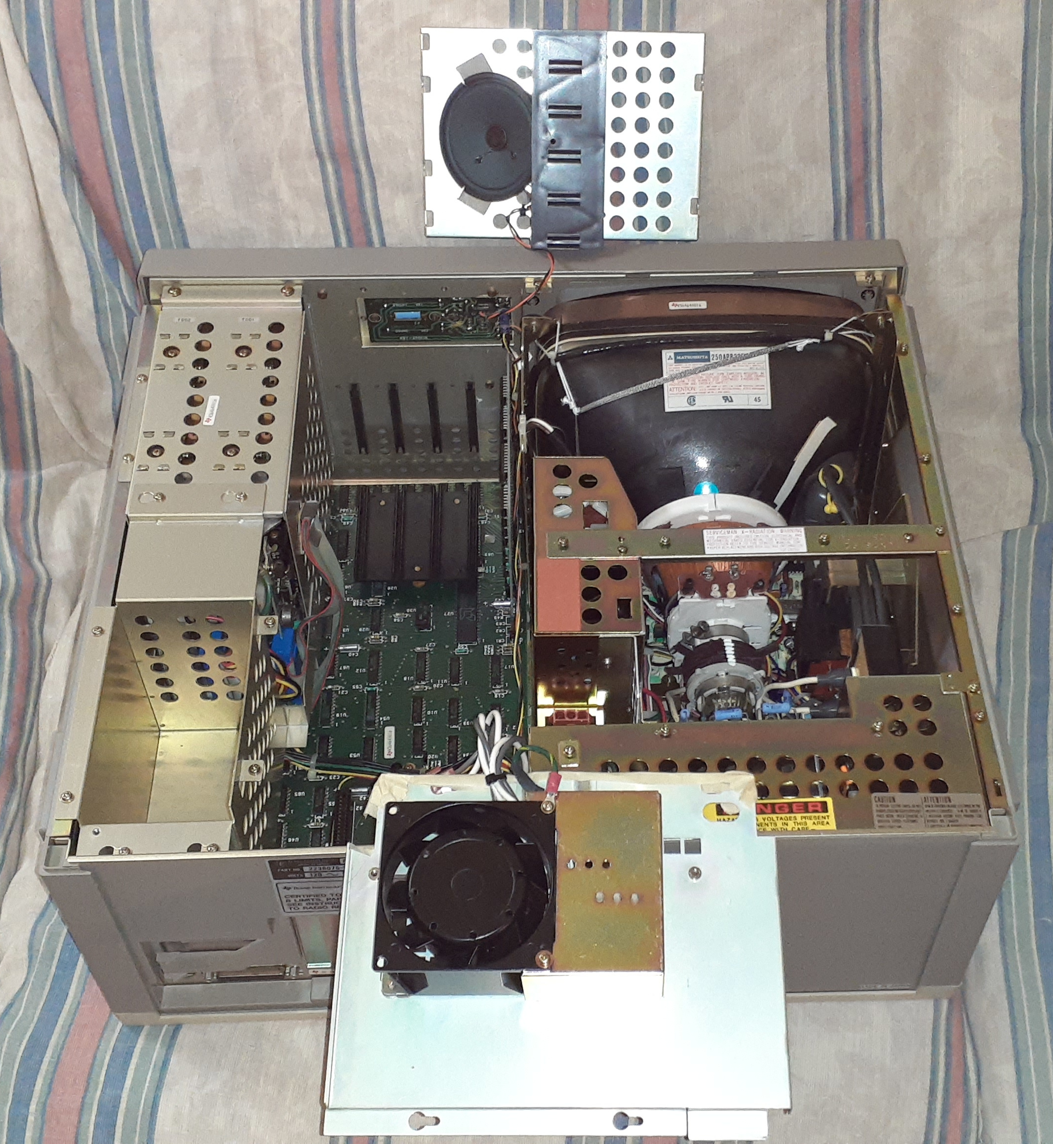
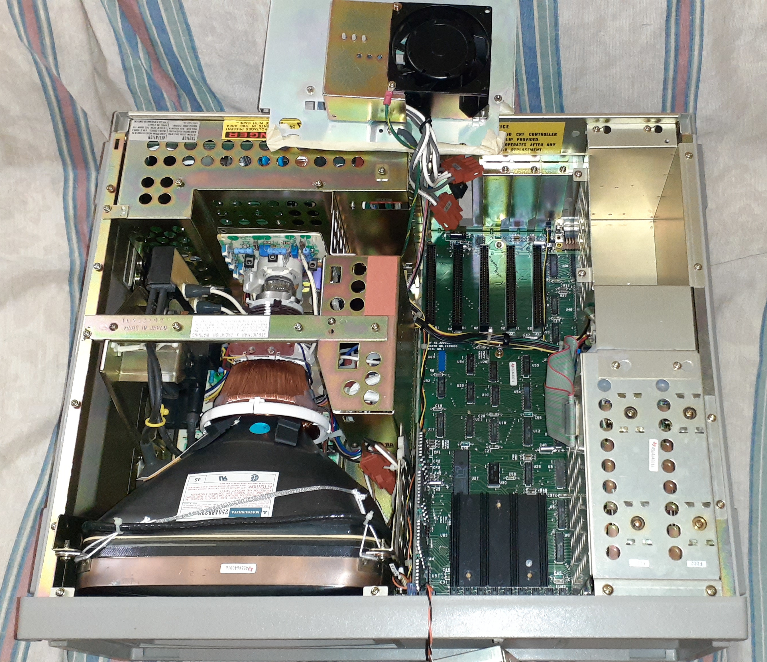
Some pictures of the inside with some covers removed. Motherboard is same as desktop machine. Click on pictures for full size.
Under test.
Repaired video board.
Chip tester. The source code.
Repaired TI running. The fan on top takes almost 2 minutes to stop spinning
when you power it off. Looks like bearings are still good. Fan air noise is
pretty loud.
The empty pocket in lower left is for storing the power cord. There is a
door in the top to access it.