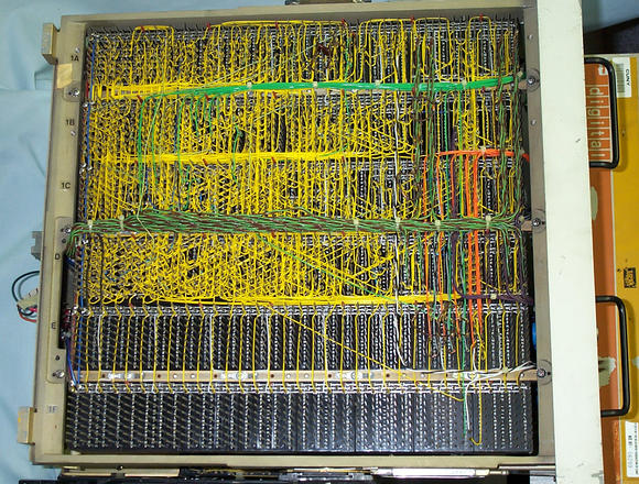
This is the AX08 wirewrap backplane. Closeup of backplane. (140K) The yellow wires are the signal connection between the boards. The green and brown or black and grey wires twisted together are the analog inputs. The twisting helps prevent noise pickup. The green wires are the digital inputs and outputs. The orange, black, purple, and white wires connect to the front panel controls. You can also see some resistors, diodes, and capacitors attached to the backplane. These are configuring some of the cards. The labels on the left identify the card rows and the little red covers on the wirewrap pins mark every fifth row to make it easier to find the connection for trouble shooting.
Back to Previous page All of PDP-8 AX08 Laboratory Peripheral pictures
Feel free to contact me, David Gesswein djg@pdp8online.com with any questions, comments on the web site, or if you have related equipment, documentation, software etc. you are willing to part with. I am interested in anything PDP-8 related, computers, peripherals used with them, DEC or third party, or documentation.
PDP-8 Home Page PDP-8 Site Map PDP-8 Site Search