 This is the status of testing the DIP version of the MFM hard disk reader
and emulator PCB. The peer review did not
find all the errors.
This is the status of testing the DIP version of the MFM hard disk reader
and emulator PCB. The peer review did not
find all the errors.
This is the status of testing the DIP version of the MFM hard disk reader
and emulator PCB. The peer review did not
find all the errors.
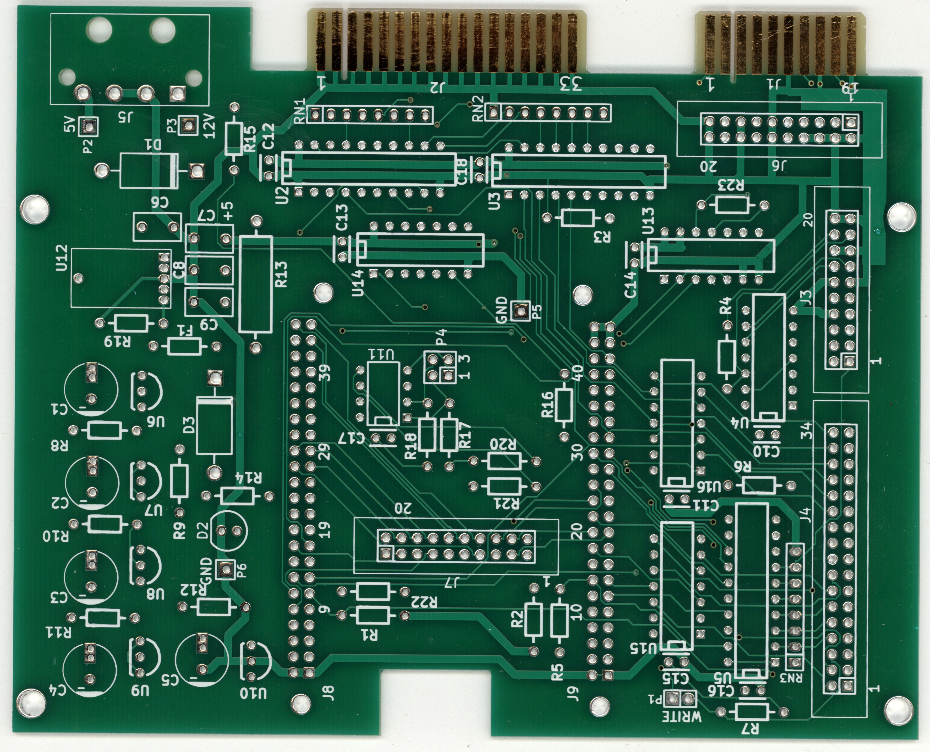
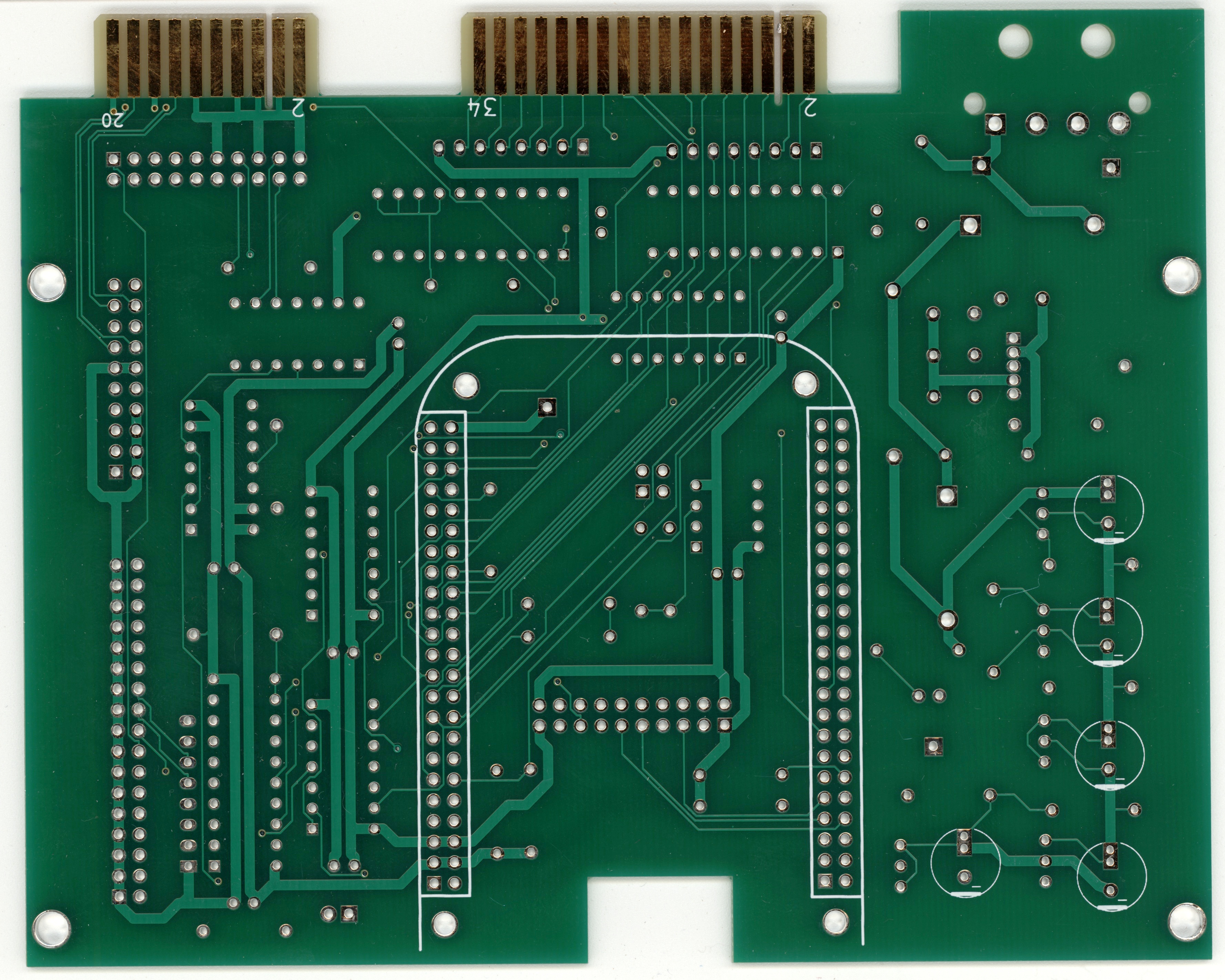
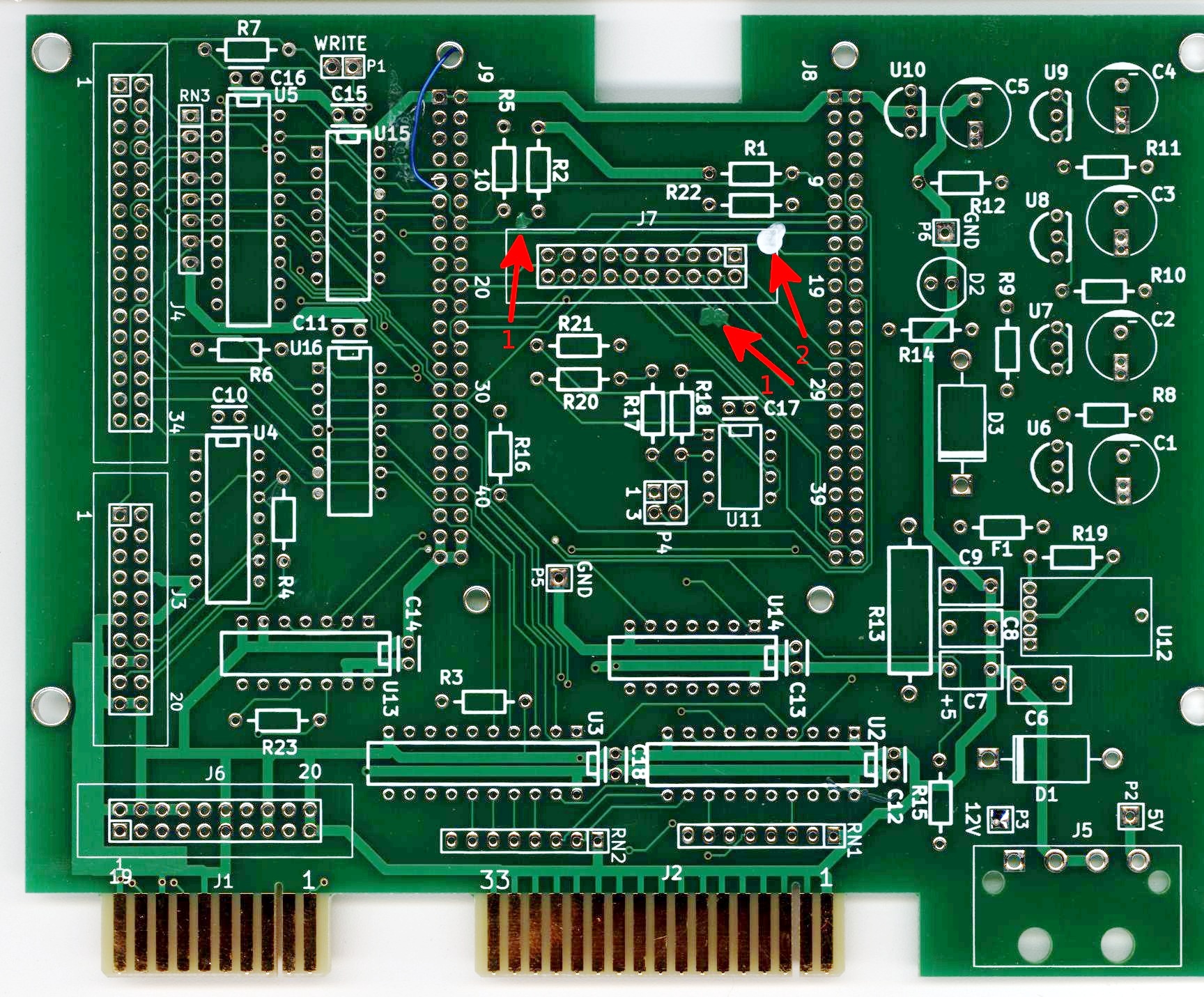
Bare board (click pictures for larger version)
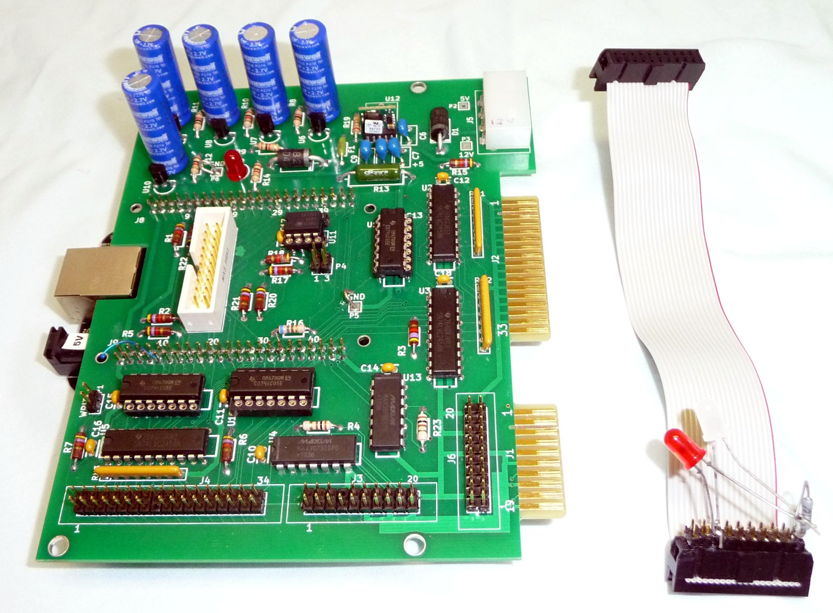
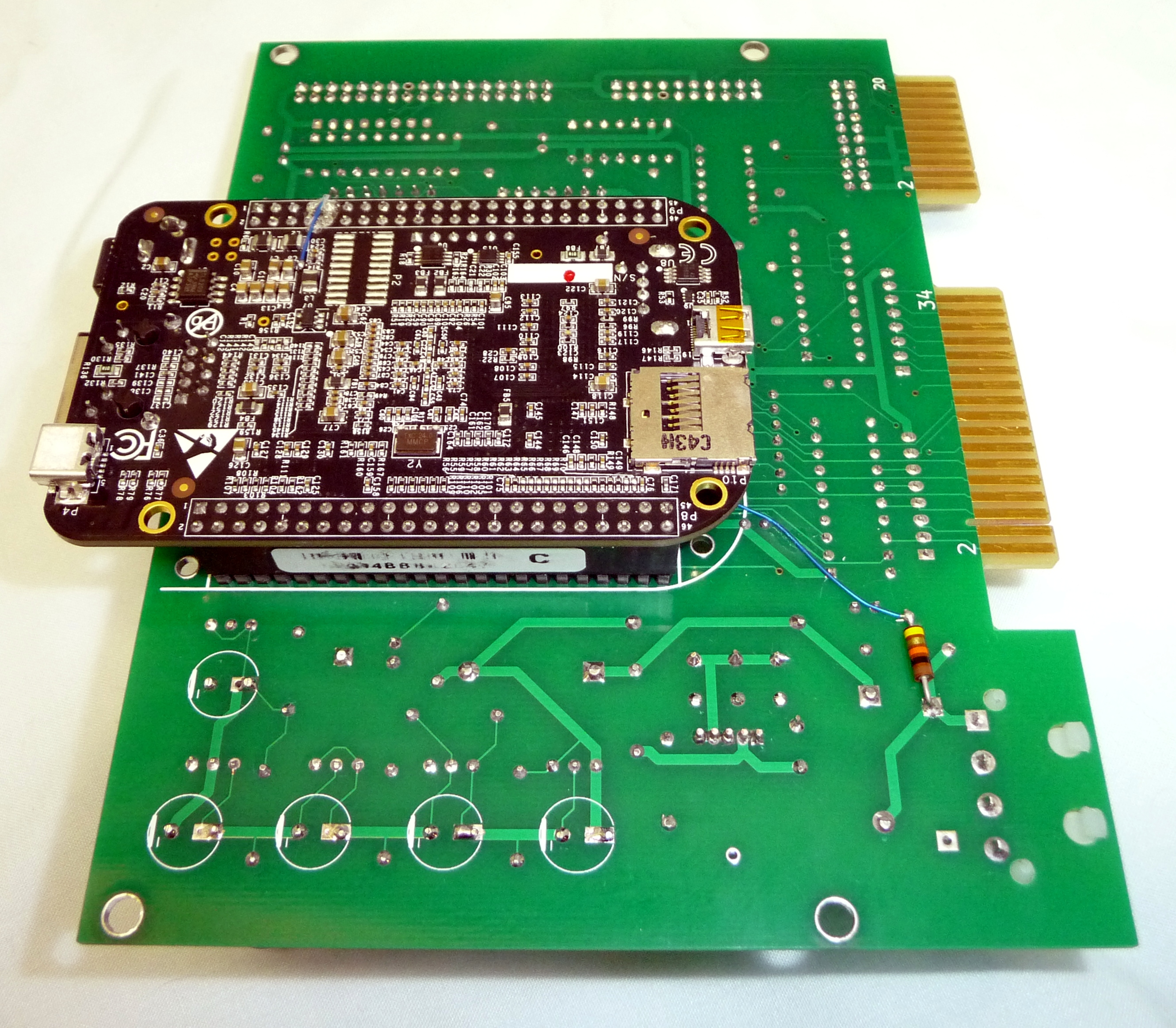
Assembled board and cable for testing drive activity LEDs. A couple parts such as J7 are parts I had around and not what is called for in the parts list. A couple chips are also socketed for my testing.
Information on building and testing board
There are three options to deal with this problem:
1) Don't power down for short times. If you power up your computer and only power it off when you are done then this will not affect you. If you power off for short times to reset the computer after crashes or need it to come back after AC line dropouts then you need one of the later options. The time to start shutting down the BBB is configurable so if you are using the 10F capacitors you can delay shutdown for several seconds to allow short power cycles to reset the computer without shutting down the BBB.
With the 10F capacitors and halting the processor instead of powering it down, it takes about 40 seconds until the power drops low enough that the board will restart when power is reapplied.
2) Add a chip to generate the power button signal to power the board back on. This pulls the power button signal low if the input 12V is present when 3.3V is not.
3) Use a battery on the BBB instead of the capacitors. I haven't tried this solution and it requires modification of the BBB so may not be a good choice. Also the terminating resistors RN1, RN2 would need to be changed to 130 or 150 ohms powered by 3.3V to prevent the possibility of unintended writes when power is lost. The battery will not provide power to the terminating resistors so all the control signals will look like they go active.
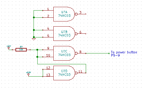
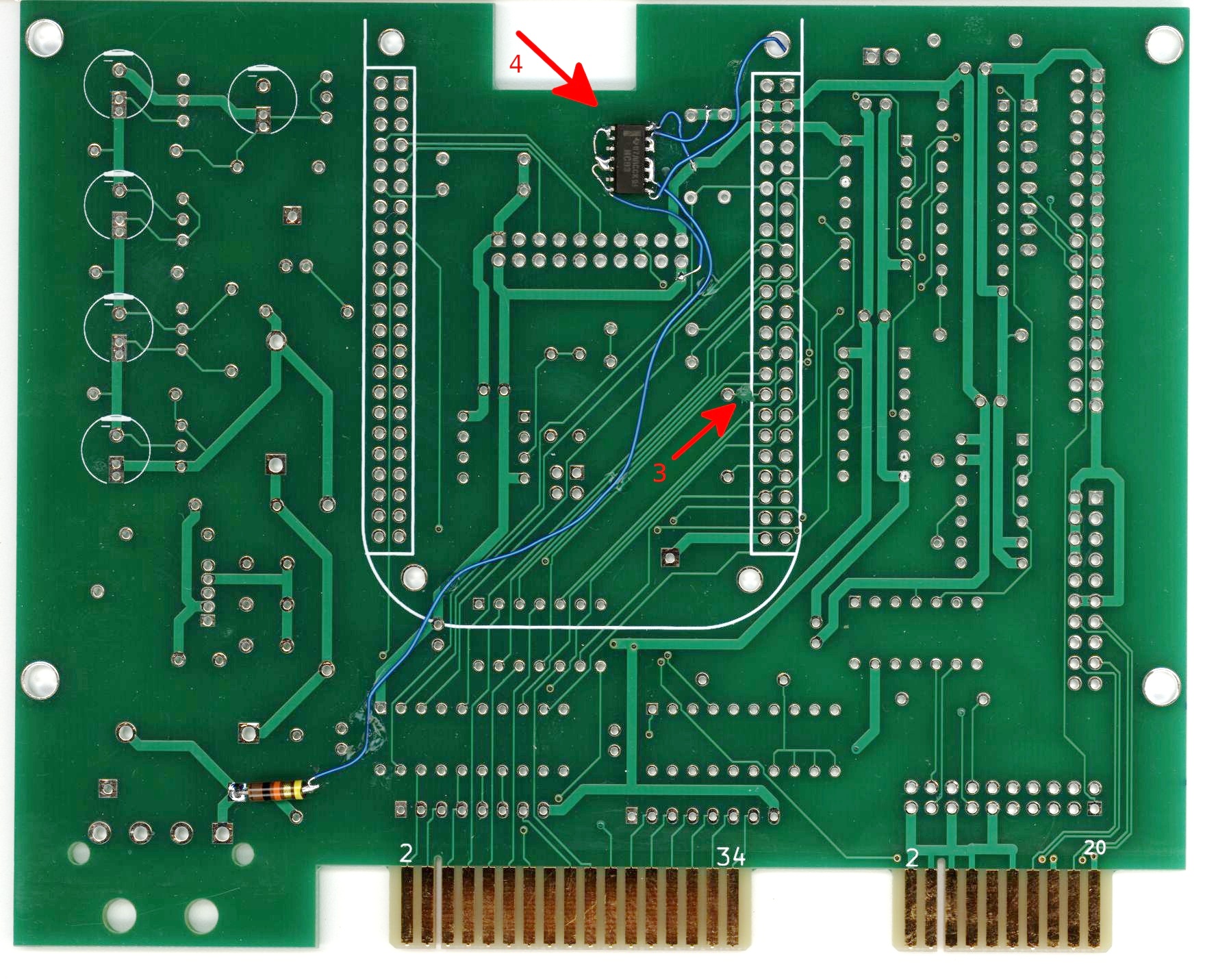
Here is the change I will use for reworking the existing boards, implementing
the second option. Most of the reworked boards also have pins 3 and 6
grounded since it was quicker to solder all the pins on that side
of the chip to the ground wire.
This is the change I will use for the surface mount board. I had bought
the HC03's before I switched to the ACT05's and noted they could be used
to avoid needing another part type.
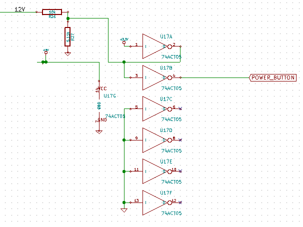
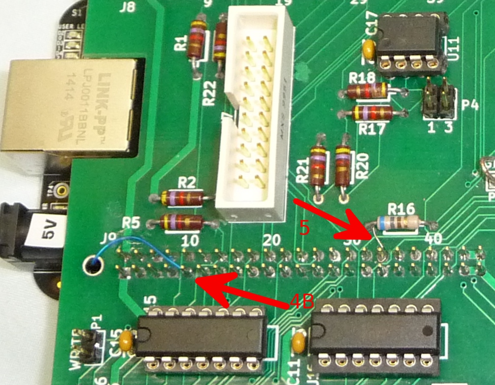
The pin-out will be changed for the surface mount version.
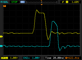 The MAX3079E is a little slower than desirable. The MFM data is equivalent to
a 20 Mbps rating of the transceiver. This part is rated at 16 Mbps.
It reduces the 40ns
pulses from the controller I was testing with to 30ns. The design is only
sensitive to rising edge timing so the pulse shortening isn't a significant
issue, as it does not seem to introduce significant data pattern edge jitter.
The MAX3079E is a little slower than desirable. The MFM data is equivalent to
a 20 Mbps rating of the transceiver. This part is rated at 16 Mbps.
It reduces the 40ns
pulses from the controller I was testing with to 30ns. The design is only
sensitive to rising edge timing so the pulse shortening isn't a significant
issue, as it does not seem to introduce significant data pattern edge jitter.
For the surface mount boards I will switch this part to surface mount. That
will give the option of using a faster part such as Linear LTC2852 or
TI SN65HVD33, both rated at least 20 Mbps. It also gives other sources if
the Maxim part has a long lead time. These parts are also slightly cheaper
than the DIP part.
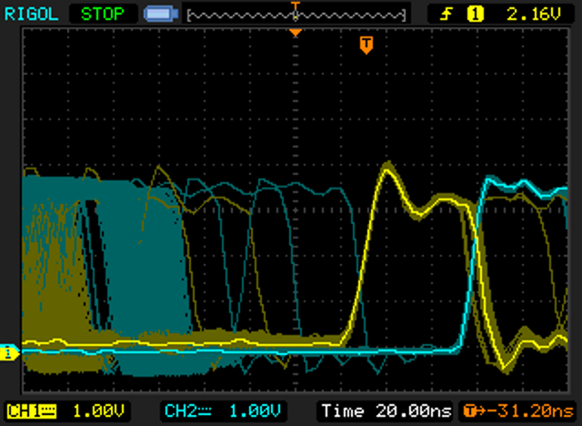
I also tested with a DIP capacitor which greatly reduced the noise. It did not significantly change the output signal.
The transmit signal was left on when receiving so the output signals wouldn't be floating. One of the controllers I was working with turns off its write data lines when write is not active so floating lines may not be an issue. The outputs can be turned off by cutting the trace to pin 4 and then jumpering pin 3 to the output enable pin 4.
The shorter trace length for the surface mount part will reduce the power
noise.
I will investigate the enable change more before deciding if I change this
for the surface mount board.
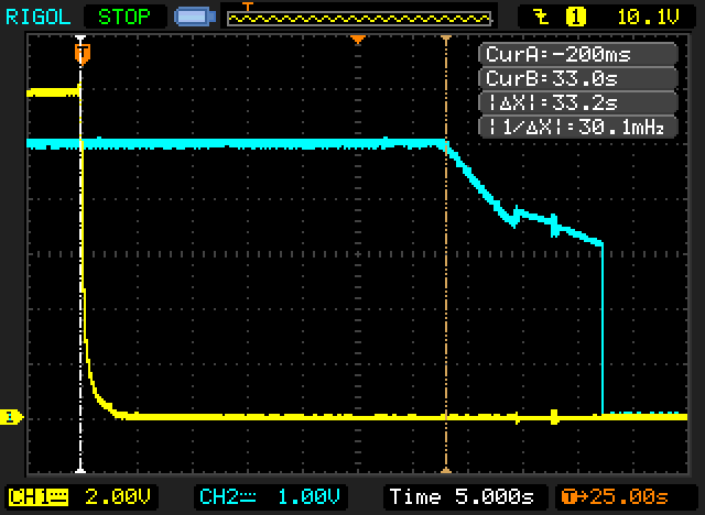
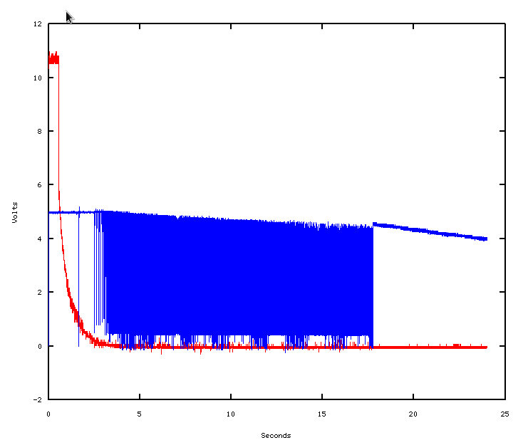 Also when input power goes away the slow discharge of the capacitors
can cause it to keep turning on and off then turn back on with decaying
output voltage. The BBB will shut off during the oscillating power
but will power back up during the decaying power until it goes too low.
I think this data was with a resistor from enable to ground which made the
behavior worse. Other configurations the oscillation was only for a
couple seconds.
Also when input power goes away the slow discharge of the capacitors
can cause it to keep turning on and off then turn back on with decaying
output voltage. The BBB will shut off during the oscillating power
but will power back up during the decaying power until it goes too low.
I think this data was with a resistor from enable to ground which made the
behavior worse. Other configurations the oscillation was only for a
couple seconds.
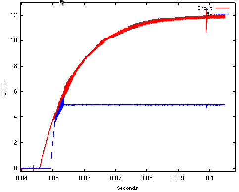
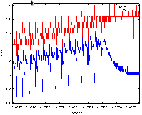
The enable pin can be used to disable start up until the input voltage is
at a particular value. If a pull-up to 5V is used in addition for positive
feedback the oscillation is prevented. A 5.11k to ground and 51.1k to 5V
gives clean power up and down transitions.
 The Murata OKR-T/1.5 does not oscillate during the power down, it
just goes out of regulation when the input voltage drops too low. The
BBB seems happy with this part so for this board only the Murata
part should be used. The Murata datasheet does not document using the enable
pin to change the shutdown voltage. A little testing seems like it may
work but will require different resistors. This will be investigated
further later.
The Murata OKR-T/1.5 does not oscillate during the power down, it
just goes out of regulation when the input voltage drops too low. The
BBB seems happy with this part so for this board only the Murata
part should be used. The Murata datasheet does not document using the enable
pin to change the shutdown voltage. A little testing seems like it may
work but will require different resistors. This will be investigated
further later.
The two resistors will be added to the surface mount board.
Using Rev C Debian BBB I tested with a 80MB emulation file for emulating a 32MB disk drive. The time to sync after copying the file to flash is 8 seconds. Using my disk access routines to sync the file after updating the entire file is 16 seconds. It is 24 seconds to sync after writing non consecutive 1/5 or 2/5 of the cylinders.
The BBB has internal flash and also can use microSD and USB sticks. The larger flash on the rev C should allow it to work fine for image storage. If you are trying to run 24/7 with lots of writing you might want to use external flash to prevent the possibility of wearing out the internal flash. Many microSD cards are very slow especially for random writes so try to find one people have found gives good performance and test. With a Samsung class 6 micro SD card I got similar results to the internal flash. With a Sandisk extreme USB 3.0 16GB stick the sync time was 4 seconds. The Sandisk USB required an extension cable to mate. Longer pins for the BBB connector would allow it to mate directly.
The internal flash writing time for my rev B BBB is significantly longer. The file system is over 90% full which I think is making it slower.
5F capacitors can be installed and still fit in a half height drive bay. 10F capacitors can be installed but will not fit in a half height drive bay unless they are mounted laying down on the bottom side of the board. This will involve running wires to one of them.
The following results are measured with the LDO03C DC/DC converter,
11.9V input power and emulator code running but
otherwise idle. The Murata OKR-T/1.5 run times are similar.
3F capacitors run time is 7.6 seconds. This is enough to power down
the BBB but not enough if any significant data needs to be written to
the on board flash.
5F capacitors run time is 14.2 seconds. This is likely sufficient with a rev C board for normal operation though a lot of writing of random sectors may be able to have enough data to write that it can't be completed before power is lost. Various parameters can be changed to reduce the amount of data buffered to prevent data loss.
10F capacitors run time is 32.4 seconds. This should cover any realistic amount of memory needing to be written unless a really slow microSD card is used.
The DIP version could get longer run time by switching off the power to terminating resistors or switching to 130 or 150 ohm pull-ups to 3.3V. This could be done to the existing board but probably isn't worth the effort.
The surface mount board will allow 10F capacitors to be cleanly mounted on the bottom of the board. I will likely switch to 3.3V for the terminating resistors RN1-RN3.
I may look at changing J6 orientation for the surface mount board.
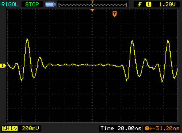
 The yellow trace is the BBB 3.3V A rail with 74F07 for U14-U16. The
white trace is the expansion_12 signal. The 74LS07 with lower input
current is better but still raises the rail some.
The recommended chip to use for U14-U16 was changed from 74F07 to 74ACT05
to prevent powering signals to the BBB before its power supplies
are on.
The manual says signals should not be powered before its power
supplies are on. I had some intermittent failures where the BBB powered
up but didn't boot. It was infrequent enough that it wouldn't
reproduce enough to troubleshoot the cause. I haven't seen it after
switching to the 74ACT05.
The CMOS part has insignificant input leakage and provides 24 mA
output drive.
The yellow trace is the BBB 3.3V A rail with 74F07 for U14-U16. The
white trace is the expansion_12 signal. The 74LS07 with lower input
current is better but still raises the rail some.
The recommended chip to use for U14-U16 was changed from 74F07 to 74ACT05
to prevent powering signals to the BBB before its power supplies
are on.
The manual says signals should not be powered before its power
supplies are on. I had some intermittent failures where the BBB powered
up but didn't boot. It was infrequent enough that it wouldn't
reproduce enough to troubleshoot the cause. I haven't seen it after
switching to the 74ACT05.
The CMOS part has insignificant input leakage and provides 24 mA
output drive.
The CD74ACT05E DIP part is currently readily available though it looks like Digikey and Newark will stop carrying it after stock is exhausted. Mouser and Avent have lots and don't seem to be planning to stop carrying it.
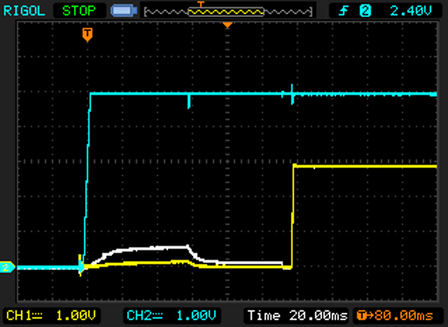 The white trace is with 74LS07 and the yellow trace with 74ACT05.
The surface mount version of the 74ACT05 has better availability. I need to think more about what is surface mount on that board version.
The disk reading seems to have similar ability to read marginal tracks as the normal controller though I don't have the correct combination of drives with errors and software to report the errors to fully verify.
In further testing I found that if continuous random writes are done it causes the emulation process to block and the host gets timeouts. I have added buffering and intentional write rate limiting to help. There is a conflict between the buffering and having sufficient run time on poweroff to write all data to the flash and shutdown the board.
You can tune this with the buffer command line option and the logfile.txt mfm_emu writes when it exits. I think for normal classic computer usage the buffering will be fine. With continuous random writes I did see it take 12 seconds between writes to internal flash so you can still have problems with the default settings. If you increase the buffering significantly you may need to wait at least 45 seconds after large amount of writing before powering off the computer. You may also use a fast USB stick. I found Sandisk extreme USB 3.0 16G works well.
In theory there are settings that can be changed on how the operating system buffers the data. I wasn't able to improve performance by changing them. Reducing vm.dirty_expire_centisecs will write the data out sooner. If you are needing to wait before powering off lower values will require less wait.
In testing this a saw a few times where things paused with the drive light on for a little while. I have not been able to reproduce it to investigate. It seems to work well but there is probably still low frequency of occurance bugs left.