SA1000 adapter board assembly
See here for usage information
I have updated board to rev D due to the oscillator I used on rev B being
long lead time. Make sure you use BOM for the board revision you have.
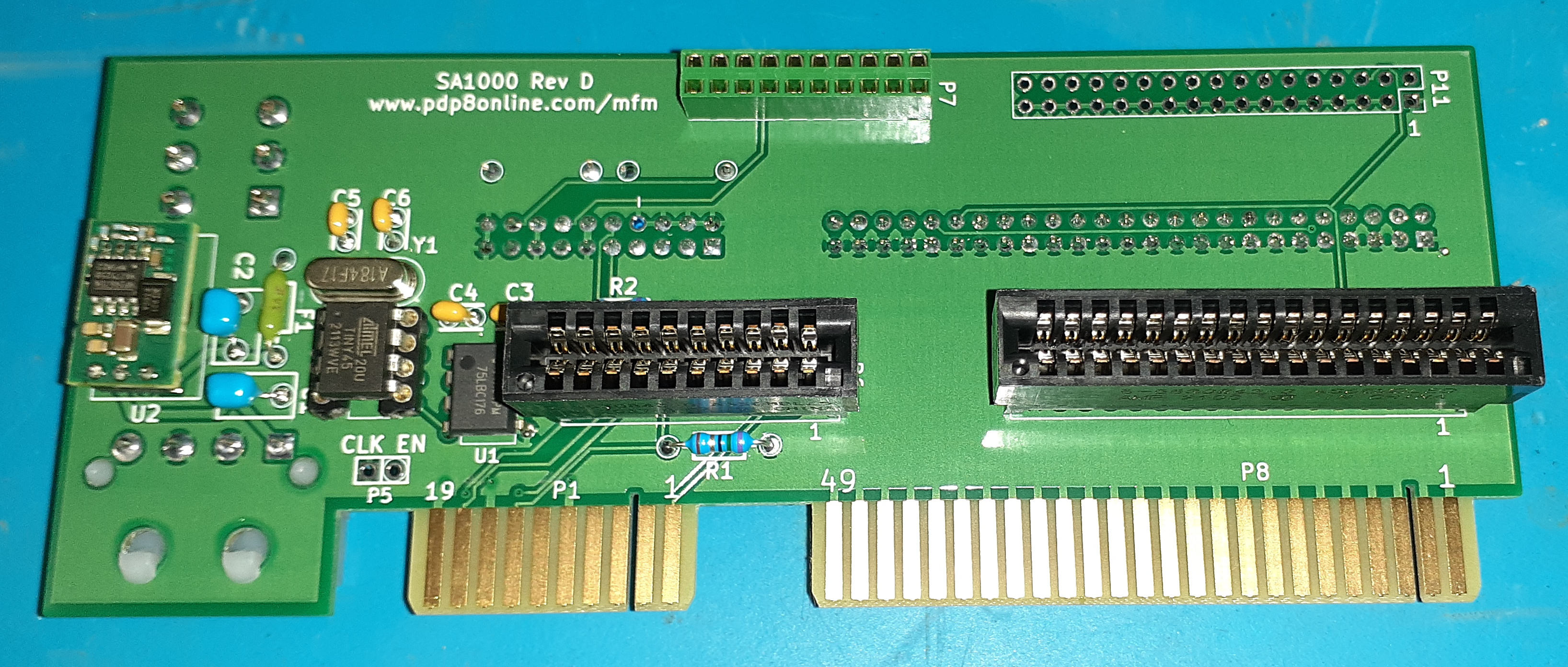
For new rev D board
Missing one connector
Mouser BOM
Digikey BOM
Note: The programmed ATTINY chips I shipped with SA1000 rev D boards before
October 17 2021 are programmed for use with 18.432 MHz Crystal. I used
Abracon ABL-18.432MHZ-B2. Purchase that crystal instead of the 9.216 MHz on
the BOM. Since the 20 MHz ATTINY45 are out of stock I switched to the lower
frequency that will work with the 10 MHz parts available. I will ship future
programmed ATTINY45 programmed for the 9.216 MHz crystal.
Arduino sketch for board. If you are using
the 18.432 MHz crystal you will need to edit the loop_count_pll value as
commented. The comments at the top are my notes on programming. I can
provide a programmed part with board.
The board files are here and
information on
files is here.
See board license
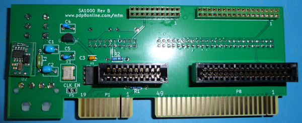
For old rev B board
Digikey is the only place I found an oscillator which could be programmed
to the needed frequency so I am only providing a
Digikey BOM. Edit as
needed for your usage. Add as ordering note Program oscillator 510CAB-AAAG to .27125 MHZ.
If all the parts show up as invalid refesh the
page. It seems to sometimes do that.
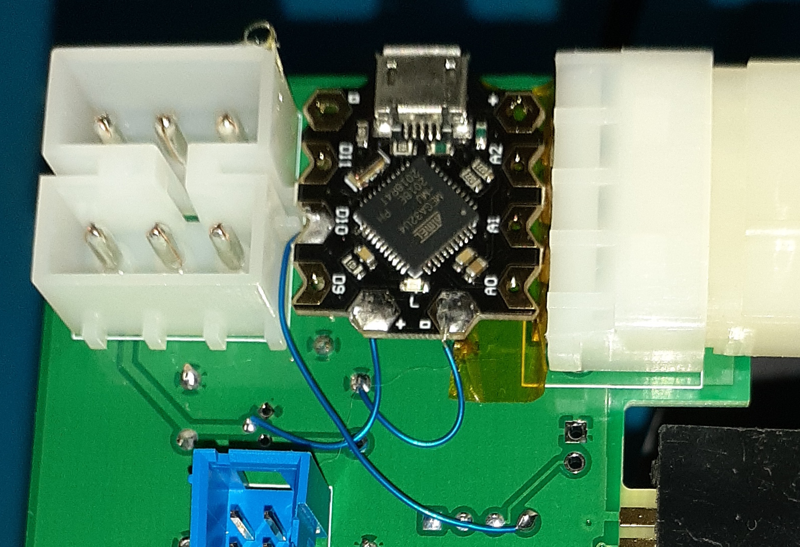
The oscillator is out of stock and likely to be for a number of months. I
use an Arduino beatle
The SA1000 manual says it wants a 271.250 kHz +- 0.1% clock. Theoretically
this could be programmed to 0.02% of the desired frequency. The one I bought
was 0.16% off. It likely has a ceramic resonator thats not that accurate.
The clock is used for up to speed detection and step rate control so 0.16%
should be close enough. It worked fine with my drive. Don't know how far
off other boards will be. Arduino sketch for board
I used some tape to make sure it didn't short to the connector pins and some
hot melt under to to keep in in place and above the component pins. You can see
the three connections it needs.
The board files are here and
information on
files is here.
See board license
If using the short connectors for P7 & P11 in the BOM R3 and R4 will
need to be installed on the opposite side of the board from how the
silkscreen indicates for the unlabled revision of the board. The silkscreen
was corrected for rev B
X1 pin 1 is in the upper left. On the sikscreen its in the upper right.
X1, U1, U3, C3-C5 only needed for reading Shugart drives which need external clock.
Emulation for all drive or reading Quantum drives don't need the clock.
If you are only using the board for reading or only for emulation you can
not install some of the connectors.
P5 is not needed.
Front of board
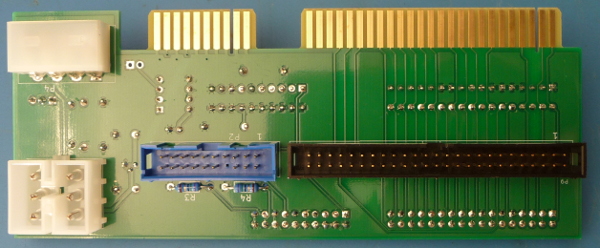
Back of board
Feel free to contact me, David Gesswein djg@pdp8online.com
with any questions, comments on the web site, or if you have related equipment,
documentation, software etc. you are willing to part with. I am
interested in anything PDP-8
related, computers, peripherals used with them, DEC or third party, or
documentation.
PDP-8 Home Page
PDP-8 Site Map
PDP-8 Site Search

