You should know your computer memory is good before running this program. Available from osi.marks-lab.com tools. See TestMem.zip. Also Osiweb.org has a memory test for video-based computers.
The code V1.04 is on github here and as a zip file here. Mark made some improvement which I haven't had time to test but should be the best version to use. They are on his site and I have a local copy here. Floppy test 1.04u.zip
Load files for the OSI are provided. If you wish to reassemble use the A65 assembler from Mark's OSI software archive. The make_test file builds it for me under Linux. I have a script convser I used to make the serial load file. You can also use OSIALod from the above page.
This program is intended to work with an Ohio Scientific computer with either serial console or video board and at least 16k memory. If used the video board must support at least 64 characters wide. It has been tested on a C2 with 505 CPU, 540B video and serial console with SYNMONV1 ROM. If you run into problems and want to help debug it on other machines contact me at the link at the bottom of the page.
For serial at the H/D/M prompt hit M and then upload the program over the serial port. Since the OSI echos each character you will need an upload program that waits for the character sent to be received or that can add delay between characters to prevent data overrun. Lowering the baud rate won't help since the sending slows down also. Sending with two stop bits may help. After loading is done type G to start the program running.
For video at the H/D/M prompt have caps lock on then hit M then L then upload the program over the serial port. I've been using a 505 processor card and the serial port on it. For other machines you will need to figure out how to upload the program. I think with video it's fast enough that it will keep up with the serial data. The program autostarts when loaded through the video monitor.
After it's started the program will then print HIT ANY KEY TO SELECT CONSOLE DEVICE. Hit a key and then you should get the main menu.
 OSI DESTRUCTIVE Disk Test
--------------------------
1. Test Disk
2. Test Track
3. Select Drive
4. Set Drive Type
5. Set Pattern and passes
6. Toggle read only
7. RPM Test
8. Status screen
9. Exit

Drv=A/8 Pattern $18  Passes 1 Normal test R/W >
Note the 'DESTRUCTIVE' - do not feed it data you're fond of.
First verify the setting are correct. The last line says we are testing drive A which is 8" with pattern hex 18 and doing one pass with normal test in read write mode. Options 3-6 allow changing the settings.
Since I just finished this program and haven't done that much fault finding with OSI floppies some of the suggestions for problem causes may be wrong. Some is based on faults I have seen on other machines.
Head unloaded RPM: AVG   360.40  MIN  360.05  MAX  360.57
Head loaded   RPM: AVG   360.31  MIN  359.97  MAX  360.57
When first entered all bits should be zero. The track number printed is not accurate until you hit Z with the drive selected. Below is after hitting S to select the drive. The bits are the logic level of the signal. The actual signals are active low so low level = 1. The drive you have chosen should have RDY 1. If the heads are at track TRK0 should be 1. Hitting Z should move the heads to track 0. U should move the head to track 1 and TRK0 should go 0. D to move it back should set TRK0 back to 1. The program doesn't prevent you from stepping below track 0 or above the maximum track. I've heard that on some drives, this can affect the alignment so best not to do that. Index will go 1 occasionally. W will write all ones to the entire track until W is hit again to stop it. Both write enable and erase enable will be active. You can use test equipment to check the various signal lines.
CMDS:(S)el (H)ead (W)rite Step:(U)p (D)own (Z)ero (E)xit

R T F S R W S I
D R A E D R e N
Y K U C Y I l D
1 0 L T 2 T 1 E
    T     P   X
1 1 0 0 0 0 0 0  TRK  0
The main test is 1 test disk. This will first write all tracks with the specified test pattern then read all the tracks and print out if any errors are detected. It will repeat for the specified number of times. You can also select to only do the read test with 6 toggle read only. The disk for the read only test must have been written by this program.
For track without any error it will print.
RTRK ## 0The last digit is the difference between the expected number of bytes and the actual number read. Missing bytes is negative. Reading more bytes than needed is not considered an error. Up to one junk byte found before the start of track byte will be silently discarded. If errors occur they will look like these:
RTRK 26 ----6 2618 18 0CP 2619 18 86P 2620 18 D5  2621 18 EDP 2622 18 FE   476
RTRK 61     0 2645 18 18P    1
The first line says we read 6 bytes less that we wrote. The first byte in error was byte 2618 and the expected value was $18 and the value read was $0C and it had a parity error. The error data will repeat for the number of errors that will fit on a line. Last value says 476 total errors were found on the track. The second line is an error in only one byte.
Seeing if the errors are mostly repeatable vs random and if they change each time the disk is rewritten may give clues to the error cause. Errors that repeat at the same location are likely media defects.
The scope test version is intended to trigger a scope when an error is detected. The trigger will be a negative pulse on the fault reset line. The start bit of the word in error is around 76 to 86 microseconds before fault reset falling edge for my 1 MHz 505 processor. Faster processors will reduce the delay but not the 44 microseconds to shift in the serial byte.
The error printout in this mode is like this:
RTRK 26 2619 GOOD 18 BAD 58
Hit space to reread E to exit or other key to continue >
This says that byte 2619 was bad with the expected value 18 and the value read 58. It also checks for parity errors but doesn't currently print if it got one so it's possible for good and bad to be the same if the error was in the parity bit. Only the first error is reported. My format is about .8 us delay from index rising edge to first byte written then 3600 bytes of data for 8" or 2167 bytes of data for 5.25. The first byte is always $5A and the second byte the track number starting at zero. The rest of the bytes are the specified pattern.
OSI uses a non standard disk format with the data read and written with a UART and the drive having an on board data separator. My test uses 8 bits even parity 1 stop bit. If you want to know detailed information on the OS-65D format see the Compute's Gazette 20 and 21
Serial data idle level is a 1/high with the start bit 0, the least significant bit sent first and parity after the 8 data bits. The last bit is a stop bit which is a 1.
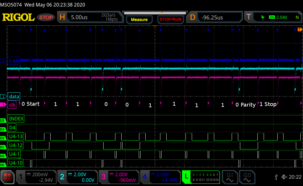
First find the start bit. Picking a visually distinctive test data pattern helps. I find what I think is the start bit for the error then back up and verify the previous byte is the expected test value. The data value reported by the OSI should match the output of U4-12 clocked by U4-13 unless there is a hardware problem. Interpreting the U4 signals is shown in the second picture below. The output of U4 may not match the clock and data from the drive in the top traces. If they don't match the one shot timing should be checked. The U numbers will vary based on the board but the circuity is similar for all OSI disk interfaces I have seen.
This shows the data value $f3 as read from disk. $f3 is 11110011 binary. Since the value is read least significant bit first from left to right on the scope it will be seen as 11001111. The serial data always starts with a 0 bit. After the 8 data bits will be a zero if there were an even number of ones in the data. In this case there are 6 ones so the parity is zero. The last bit is the stop bit and it's always a 1. U4-13 is the clock bit to the UART and U4-12 the data bit. The state of U4-12 when U4-13 goes high is the value the UART will see. It can be different than the bits you see from the drive clock and data bits due to the OSI using one shots to generate the UART clock and data. If the zero is too far from the clock the one shot will time out and the data bit will be received as a one. The second zero in the data is close to this condition. Click on picture for full size.
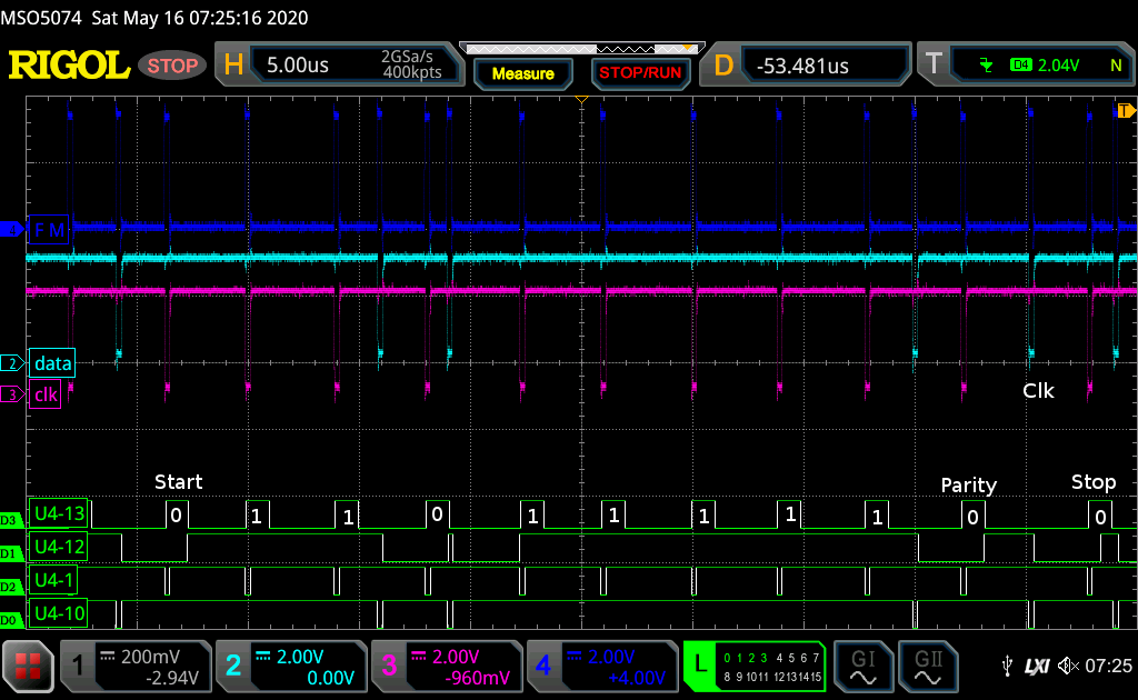
This picture shows a couple errors. The data reported by the OSI was $fb which is 11111011. You can see the two zero data bits were received ok from the drive same as the previous capture. I have marked the data bits generated by the one shot feeding the UART. You can see the second zero bit is now a one matching what the OSI reported. The parity is a zero since it is correct for the 6 ones written. With the 7 ones received it would generate a parity error. Where I marked clk you can see we are missing the clock for the one stop bit. It got converted to a zero data bit by the data separator in the drive. This would generate a framing error in the UART. My code doesn't check for that error.
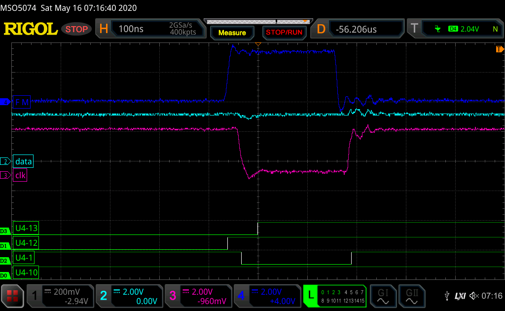
In the above capture it is hard to see that the data changed before the clock. This is zoomed in to show this. The slowest speed of the MC6850 UART datasheet specifies 250 nanosecond (ns) setup and hold time so if the clock transitions within 250 ns of the data transition it is not guaranteed if it will read the old or the new data value.
More examples of read data errors and some troubleshooting information
The code is here