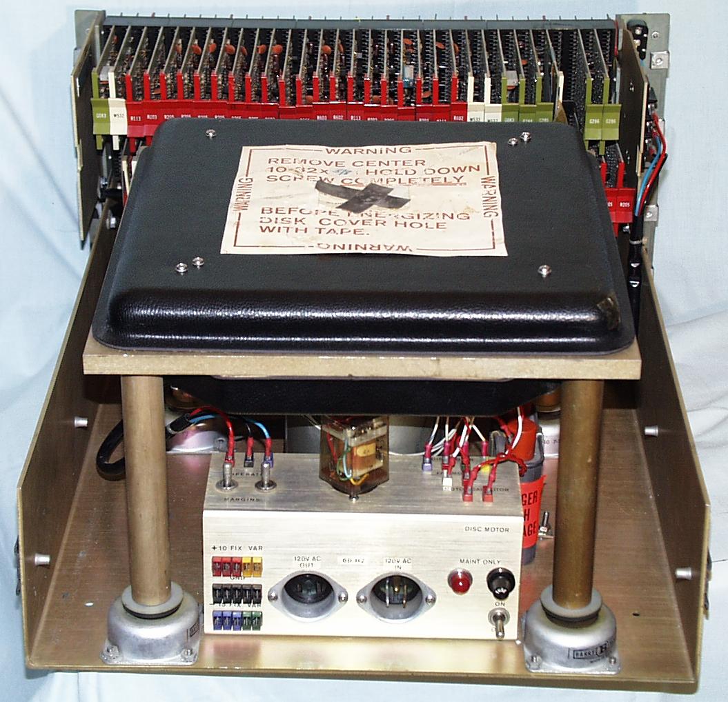
This is the back of the DF32 disk drive. The various colored connectors near the bottom are the DC power input. The unit required +10 and -15 volts. To the right is the AC power output to next drive and the AC power input. To the right is the fuse, power indicator, and power switch. The power switch is labeled maint only since these disks were normally left on even if the computer was powered off. This was because the heads (181K) land on the disk platter (180K) and cause wear when the drive is stopped. The relay above the power connectors applies power to the motor. The disk is in the black cover in the middle. and is supported by the Barry shock mounts to isolate it from the rest of the equipment. The circuit cards (205K) to operate the unit are at the top
Above the DC power input is the margin switches. To try make the unit operate reliably external DC voltages at the limits of operation were put into the VAR connections and the switches set to margin. If you adjusted the unit so it operated over the wide range of input voltages it was more likely to have low error rate at the nominal voltage.
These units can be a little hazardous. You can see the big AC capacitor with the red DANGER HIGH VOLTAGE which has covers which almost protect the AC connections but the red wires leading to it have exposed metal and all the wiring to the switch and fuse is uncovered.
Back to Previous page All of PDP-8 DF32 Disk Drive pictures
Feel free to contact me, David Gesswein djg@pdp8online.com with any questions, comments on the web site, or if you have related equipment, documentation, software etc. you are willing to part with. I am interested in anything PDP-8 related, computers, peripherals used with them, DEC or third party, or documentation.
PDP-8 Home Page PDP-8 Site Map PDP-8 Site Search